Research & development
A configurable starting point for new scan strategies, experiments and laser process development.
 Let’s build your setup
 AAGAARD AM / CONTROLLER PLATFORM
A modular bridge between your process, your software and your laser hardware. Start with a single control card. Build towards a complete machine.
01 / THE VISION
CONTROL WITHOUT A DEAD ENDThe idea behind POWDERBED is simple: give laser process development a practical, adaptable control foundation.
Bring geometry, toolpaths, scanner control and process signals together in one configurable platform. Create a research test stand, develop an application-specific machine, or explore a new control path for existing equipment.
Start with the hardware your application needs today. The expansion vision preserves the same control approach as the installation grows—from a compact box to a rack system.
A configurable starting point for new scan strategies, experiments and laser process development.
A potential fit for industrial OEM legacy systems, where interfaces and machine requirements permit.
Build control around the geometry, toolpaths, sensing and workflows that make your process different.
02 / THE PLATFORM
FROM GEOMETRY TO PROCESSHardware provides the interfaces. AMCF provides the software foundation. Application-specific build processors turn your geometry into a process.
Start with the part and the process you want to create.
Translate geometry into application-specific toolpaths and parameters.
Organize execution, configuration and connected devices.
Deliver instructions through RTC hardware to the process equipment.
THE SOFTWARE FOUNDATION
Open-source machine control, shaped around your application.
AMCF connects toolpaths, machine hardware and process workflows in one extensible software framework. POWDERBED uses this foundation to build control around your equipment, scan strategy and operator needs.
Discover AMCFOfficial overview, features & getting startedInspect the source, adapt machine behaviour and develop application-specific software. AMCF’s licensing supports proprietary extensions, allowing process expertise to remain your own.
Driver plugins separate device interfaces from machine logic. Supported hardware and custom integrations can bring scanners, sensors, cameras and other equipment into a common workflow.
Public REST APIs provide a foundation for custom interfaces, automation and integration with wider production systems.
Machine-specific process logic, configurable user interfaces and process data support research setups, retrofit projects and purpose-built machines. Monitoring and feedback can be engineered around the application.
These are capabilities of the underlying framework. The available POWDERBED functions depend on the selected configuration and application integration.
Optional sensing, cameras and process monitoring can be integrated according to the selected hardware and software interfaces.
03 / ROOM TO GROW
ONE FAMILY. DIFFERENT SCALES.Explore the proposed family. Each RTC card provides two scanner outputs and one laser output. Larger configurations extend the architecture—not just the enclosure.
The compact starting point. One RTC card and an integrated computer in a desktop enclosure for a focused process development setup.
A starting point for a single laser process or research test stand.
Discuss this configurationConceptual connection diagram. External scanners, lasers and sensors are separate equipment.
Core 1 is the hardware demonstrator presented here. Core 2 and Core 4 are expansion concepts. The rack installation is an architecture vision targeting 64–128 RTC cards; system coordination, power, cooling, network design and machine integration require further engineering.
04 / THE HARDWARE
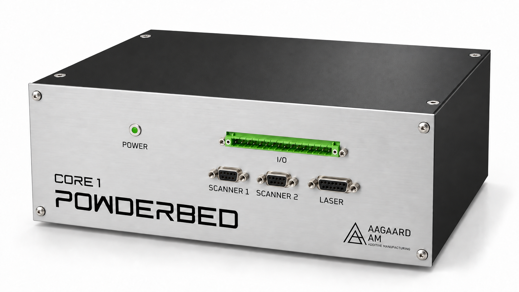
A CLEAR INTERFACE TO YOUR PROCESSCORE 1 / FRONT PANELTwo 9-pin D-sub connections for the scanner interfaces.
A 15-pin D-sub connection for the laser interface.
A configurable 16-pin connector, with signals and pin assignment selected for the application.
A green indicator with an aluminium bezel on the front panel.
16 PINS / CONFIGURED FOR YOUR PROCESS
The front I/O connector brings a selected set of RTC signals to an accessible 16-pin interface. Its wiring and pin assignment are configured around the application—whether that calls for motion control, encoder tracking or process signals.
Discuss your I/O configurationThe 16-pin connector exposes a selected signal set, rather than every RTC interface simultaneously. The final pinout, electrical compatibility and required interface electronics are defined for each configuration.
Product visualizations based on the Core 1 CAD and print artwork. Rendering details may differ from the demonstrator hardware.
05 / CONNECTED BY DESIGN
THE OTHER SIDE OF THE PLATFORMThe rear panel brings power, the controller computer and process equipment together. Its Ethernet connections create room for sensing, observation and application-specific devices.
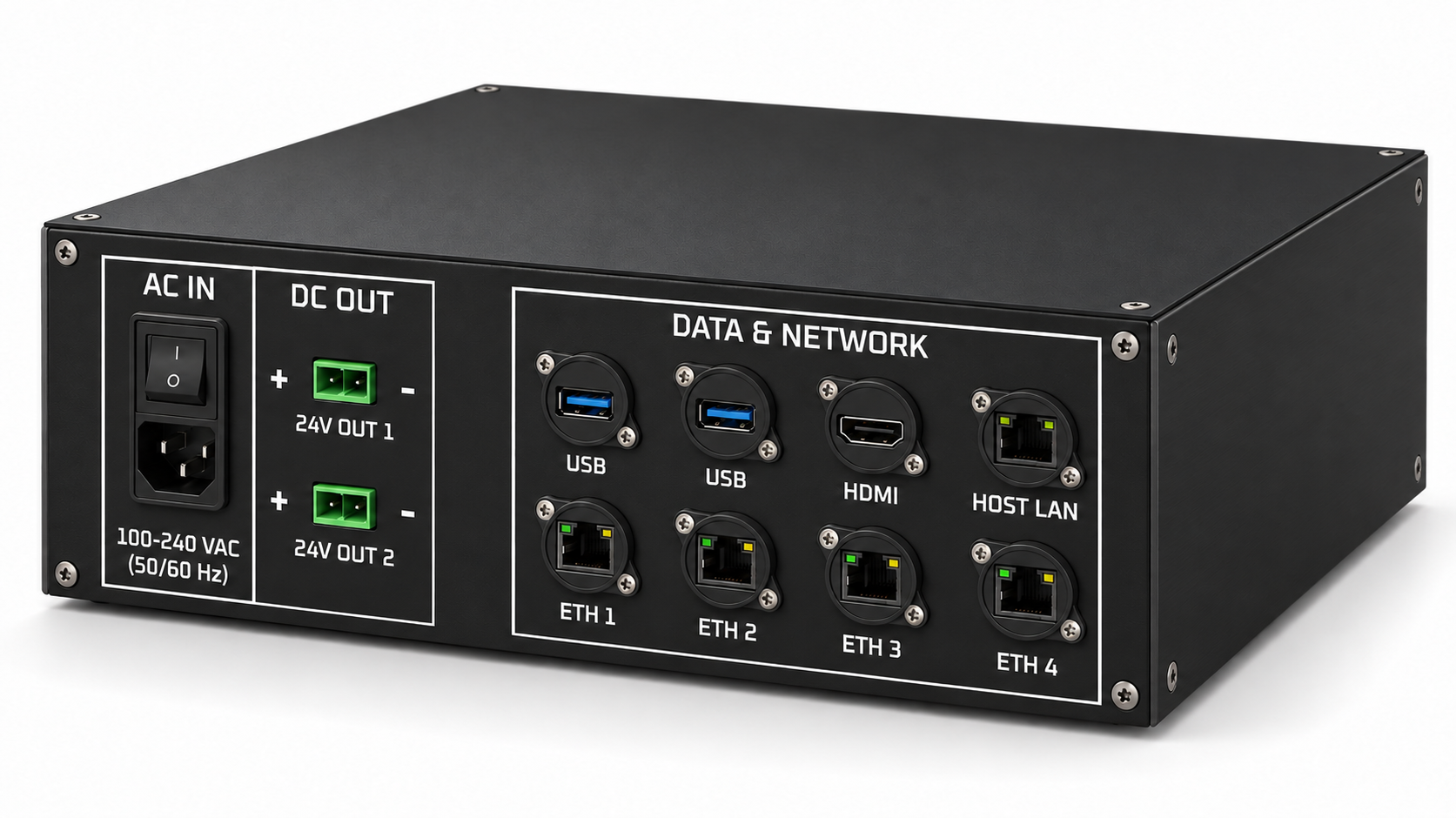
A host connection for the controller computer, with a separate equipment network in the intended architecture.
Four panel Ethernet connections provide access to the internal equipment network. They are network access ports, rather than four independent computer network interfaces.
Connect a display and USB peripherals, and supply suitable external equipment through the DC outputs within the available power budget.
The examples describe integration options, not universal plug-and-play compatibility. Device support, bandwidth and timing requirements are assessed for each application.
COLLABORATION / SENSORTHERM
SensorTherm is a collaboration partner for the POWDERBED controller vision, with its HELIOS sensor bringing a concrete process-sensing application into focus.
Explore SensorTherm HELIOSHigh-speed two-colour pyrometry
The HELIOS H422 provides an Ethernet interface alongside dedicated process signals. This opens a path for device communication and temperature measurement access within an application-specific setup.
Ethernet connectivity does not by itself establish a validated high-speed feedback loop. Real-time control requires the appropriate signal paths and system integration.
Discuss a HELIOS-based setup ↗06 / BUILT AROUND YOUR APPLICATION
The same control foundation can serve different machines, processes and research questions.
Adapt the build processor and workflow to your geometry and scan strategy.
Plan interfaces for sensors, cameras and optional process-monitoring devices around the application. The SensorTherm HELIOS collaboration is one concrete direction for temperature sensing.
Define machine-level interlocks, safety functions and operating requirements as part of the integration.
LET’S DEFINE YOUR NEXT SETUP
Tell us about your process, your existing equipment and where you want to go. We can explore the right starting point together.
Talk to SebastianFrom a desktop demonstrator
to a rack architecture vision.